1. Basic Requirements Before Cutting
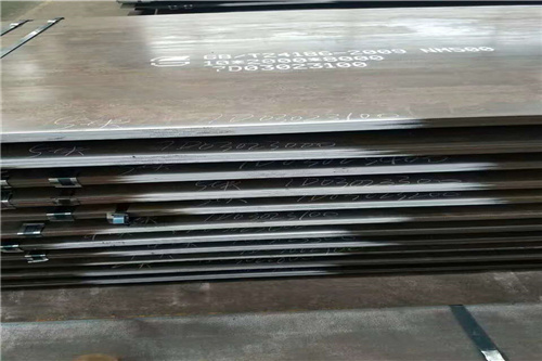
- Distinguish Material Grade and Plate Thickness
- NM400 is relatively easy to cut; NM450 and NM500 have higher hardness with significantly higher risks of cold cracking. The probability of cracking rises sharply for plates thicker than 30 mm.
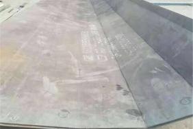
- Confirm the front and back sides of the plate: the wear-resistant layer serves as the working surface. Arrange cutting layout to avoid severe thermal shock on the wear-resistant layer.
- Plate Condition
- Avoid cutting under low ambient temperature. Preheating is recommended when ambient temperature is below 5℃.
- Clean the plate surface: remove rust, paint, oil stains and scale to prevent cut interruption, dross adhesion and blowholes.
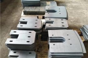
- Machining Allowance for Nesting Layout A hardened layer will form on the cut edge after cutting wear-resistant plates. Reserve machining allowance if subsequent machining is required. Reserve shrinkage allowance for long strip parts to prevent thermal deformation.
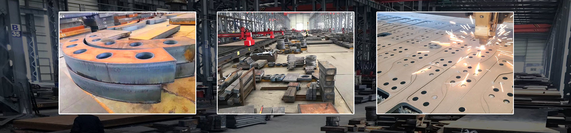
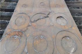
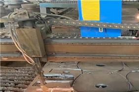
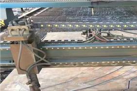
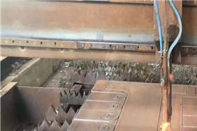
2. Flame Cutting (Most Commonly Used for Carbon-Manganese Wear-Resistant Plates)
Main risks: hardened edge layers and cold cracks
- Preheating Requirements (Core Point)
- Thickness ≤ 20 mm: preheating is optional
- 20 ~ 40 mm: preheat to 80 ~ 150℃
- >40 mm / NM500 grade: preheat to 150 ~ 250℃. Uniformly preheat along the entire cutting path instead of local spot heating.
- Cutting Parameters Adopt stable low cutting speed; excessive speed will thicken the hardened layer and induce microcracks. Select the proper cutting nozzle and guarantee oxygen purity.
- Prohibited Operations ✘ Do not pause and restart cutting arbitrarily halfway ✘ Never rapidly cool cut edges with water immediately after cutting (severe risk of cracking)
- Slow Cooling After Cutting Allow thick plates to cool naturally after cutting. If possible, cover cut edges with thermal insulation cotton. Transport and hoist workpieces only after cooling down to room temperature.
- Lead-in and Lead-out Cuts Install lead-in and lead-out tabs. Cracks often occur at cut start and end points. Do not start or terminate cutting directly on the workpiece.
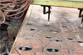
3. Plasma Cutting
- Plasma cutting delivers concentrated heat input. The hardened layer on the cut surface is thinner than that of flame cutting, yet large local temperature gradient may easily cause deformation of thin plates.
- Set appropriate current and properly reduce cutting speed to minimize stress concentration at sharp corners.
- Optimize sharp corner design: adopt rounded transitions or pre-drill holes to avoid corner cracks.
- The plasma-cut surface has relatively high hardness. Grind off the surface hardened layer if welding is required afterwards.
4. Laser Cutting
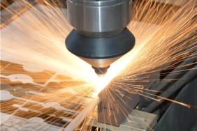
- Preferred for thin wear-resistant plates with high cutting accuracy and low deformation; low efficiency when cutting thick wear-resistant plates.
- Hardened layers still remain on edges after laser cutting high-hardness wear-resistant plates. Remove such layers by grinding if bending or welding follows.
- High-power laser brings strong thermal impact. Monitor thermal deformation of plates during mass continuous processing.
5. Waterjet Cutting (Thermal-Free Machining, Outstanding Advantages)
✅ No heat-affected zone, no hardened layer, and no cutting cracks. Suitable for parts requiring high quality, subsequent bending, precision machining or welding. ⚠ Notes:
- High hardness of wear-resistant plates leads to fast consumption of abrasive (garnet sand).
- Low cutting efficiency and higher cost than thermal cutting for thick plates.
- Fine water erosion texture exists on cut surfaces; reserve grinding allowance for high-precision products.
6. Key Post-Cutting Treatment Specifications
- Forbid immediate hammering, straightening or impact during hoisting The hardened layer on hot cut edges is brittle. Impact before full cooling easily causes extended cracks.
- Remove cutting dross and burrs Thoroughly clear dross at the bottom of cuts; round sharp edges and corners to eliminate stress concentration points.
- Pre-treatment Before Welding If welding is required: the hardened layer generated by thermal cutting must be ground off (grinding depth ≥ 2 ~ 3 mm), otherwise welding cold cracks will easily occur.
- Crack Inspection Focus on checking cut start points, turning corners and cut edges of thick plates. Visible microcracks must be removed by re-cutting; workpieces with cracks are forbidden for service.
7. Structural Design & Nesting Recommendations
- Avoid sharp internal corners on part contours; change sharp inner corners to rounded corners with R ≥ 5 mm.
- Maintain sufficient spacing between parallel cutting lines to prevent aggravated deformation caused by superimposed heat from adjacent cuts.
- Apply micro-joint bridging for slender parts; separate workpieces after cutting to reduce twisting deformation.
8. Safety Precautions
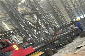
- Cutting NM series wear-resistant plates generates large amounts of smoke; ensure ventilation and dust removal.
- Long-time high-temperature cutting of thick plates may result in hot plate surfaces; prevent scalding injuries.
- Do not stack cut remnants and hot workpieces in sealed areas before cooling.