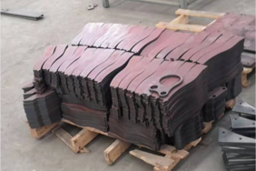
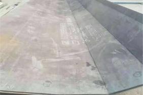
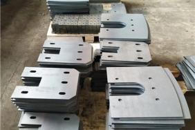
Laser Cutting Process for NM400 Wear Resistant Steel
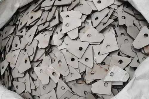
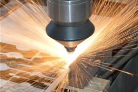
NM400 is a quenched and tempered martensitic wear-resistant steel with hardness ranging from 380 to 430 HBW. Thermal cutting tends to easily cause delayed cold cracks and edge softening. Fiber laser delivers optimal precision for machining, suitable for plate thicknesses of 6–20 mm. For plates thicker than 20 mm, fine plasma cutting or waterjet cutting is preferred due to low laser cutting efficiency and sharply increased cracking risks.
1. Pre-Cutting Pretreatment (Foundation for Crack Prevention)
1.1 Surface Cleaning of Steel Plates
- Remove rolling scale, oil stains, rust and coating from the plate surface. Polish a 100 mm wide zone on both sides of the cutting path to expose the metal substrate.
- Flatten the steel plate with flatness ≤0.5 mm/m to eliminate residual rolling stress and reduce thermal deformation during cutting.
- Do not cut plates with rust or oil contaminants. Uneven heat absorption from impurities leads to piercing edge chipping and microcracks.
1.2 Preheating Process (Core Anti-Crack Measure, Mandatory for Plates ≥12 mm Thick)
Thermal cutting cracks on NM400 are delayed hydrogen-induced cracks, which may appear 48 hours to weeks after cutting. Preheating is the most effective solution.
- Applicable thickness: Preheating is mandatory for plates t≥12 mm; 6–10 mm thin plates can skip preheating, yet low-speed cooling compensation is required for sharp corners and small holes.
- Preheating temperature: Heat a 50–100 mm wide zone on both sides of the cutting path to a constant temperature of 120–180 ℃. Measure surface temperature with a thermal gun and maintain temperature fluctuation within ±15 ℃.
- Preheating methods:
- Mass production: Fully cover the whole plate with electric heating mats.
- Single small workpieces: Reciprocally heat the cutting path with a flame torch. Avoid prolonged single-point heating, which causes local overheating and softening.
- Operation requirements: Start cutting immediately after preheating; do not resume processing once plate surface temperature drops below 80 ℃.
1.3 Equipment Selection Requirements
- Laser generator: Fiber laser with power ≥6 kW; 12 kW high-power laser is recommended for 12–20 mm thick plates.
- Nozzle: Single-layer copper nozzle with diameter Φ2.0–Φ3.0. Clean spatter regularly to prevent plate burning caused by light reflection.
- Auxiliary cooling: Equip thick plate cutting heads with follow-up water mist cooling and automatic corner air blowing functions.
- CNC system: Activate dedicated wear-resistant steel cutting programs including corner speed reduction, cooling dwell and pulse piercing.
2. Auxiliary Gas Selection & Parameters
Scheme 1: Oxygen Cutting (Mainstream, Cost-Effective)
Applicable to all 6–20 mm thickness ranges. Oxidation heat release improves cutting capacity, leaving slightly oxidized cut edges that only require light polishing before welding.
- Oxygen purity ≥99.95%; insufficient purity causes slag adhesion and brittle cut edges.
- Air pressure: 0.6–0.8 MPa for 6–10 mm thin plates; 0.4–0.6 MPa for 12–20 mm thick plates.
Scheme 2: High-Purity Nitrogen Cutting (High Precision, Hardness Preservation)
Selected for components requiring oxide-free cut edges, intact edge wear resistance and polishing-free welding. Higher operating cost.
- Nitrogen purity ≥99.999%, air pressure 1.0–1.6 MPa.
- Advantages: Narrower heat-affected zone, no oxidation or decarburization on cut edges, edge hardness maintained at approximately 400 HBW.
3. Standard Cutting Parameters by Thickness (6–20 mm, 12 kW Fiber Laser)
| Plate Thickness |
Laser Power |
Cutting Speed |
Focal Position |
Nozzle Size |
Oxygen Pressure |
| 6 mm |
6000 W |
2.2~2.8 m/min |
-1.0 mm |
Φ2.0 |
0.7 MPa |
| 10 mm |
8000 W |
1.2~1.6 m/min |
-1.5 mm |
Φ2.5 |
0.65 MPa |
| 14 mm |
12000 W |
0.7~0.9 m/min |
-2.0 mm |
Φ3.0 |
0.5 MPa |
| 18~20 mm |
12000 W |
0.4~0.6 m/min |
-2.5 mm |
Φ3.0 |
0.4 MPa |
Key Parameter Control Points
- Never adopt excessive cutting speed: Severe thermal shock at high speed generates penetrating microcracks on cuts. Excessively low speed triggers long-duration high-temperature tempering, reducing hardness and wear resistance.
- Negative focal length for all thick wear-resistant steel plates: Concentrates energy at the plate bottom to eliminate bottom slag adhesion.
- Piercing process (Avoid crack formation at piercing points) Forbid full-power one-shot blasting piercing; adopt three-stage progressive pulse piercing: ① Preheating pulse: 30% power, 50 Hz high frequency for 2 s to soften steel. ② Drilling pulse: 60% power for layered melting and erosion. ③ Full-power penetration for stable piercing. Extend lead-in line to at least 10–15 mm away from solid workpiece edges to isolate piercing stress zones on scrap material.
4. Cutting Path Planning & Anti-Corner-Crack Techniques
- Sharp Corner Optimization Design drawings with rounded corners R≥t (t = plate thickness) where possible. If drawing revision is unavailable, add an outer protective cutting loop around sharp corners: cut the outer loop first to release stress, then machine the workpiece body.
- Corner Speed Reduction & Cooling Enable automatic corner speed reduction on CNC equipment; lower speed to 30% of linear cutting speed. Pause laser emission for 0.3–0.5 s at corners while maintaining air blowing to rapidly dissipate accumulated heat and prevent overheating cracking and softening at corners.
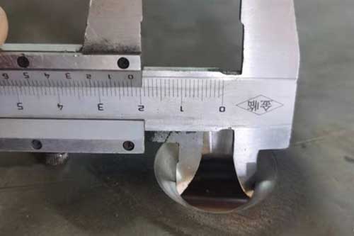
- Small Hole Machining Rules Minimum hole diameter ≥ plate thickness (Φ10 minimum hole for 10 mm plate). Adopt low-frequency pulse cutting for all small holes to reduce continuous heat input. Stagger cutting of dense holes to avoid superposed stress from consecutive heating.
- Segmented Cutting for Large Workpieces Reserve 5–8 mm micro-joints for plates over 6 meters long. Separate all workpieces after full contour cutting to minimize overall thermal deformation and stress concentration.
5. Post-Cutting Thermal Treatment (Mandatory to Eliminate Delayed Cracks)
5.1 Post-Heating & Thermal Insulation (Enforced for Plates ≥10 mm Thick)
Complete within 10 minutes after cutting; shorter interval delivers better performance.
- Heating temperature: 180–220 ℃, evenly heat the entire cutting edge.
- Holding duration: 30 min for plates thinner than 12 mm; 60 min for 12–20 mm plates.
- Function: Accelerate hydrogen diffusion and precipitation inside steel, eliminate residual thermal cutting stress and prevent delayed cracking after production.
5.2 Slow Cooling Protection
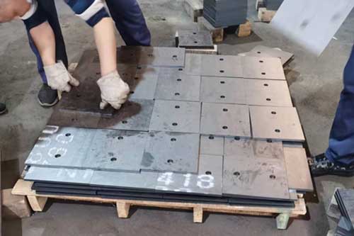
Immediately wrap workpieces completely with refractory thermal insulation cotton after post-heating, and cool naturally to room temperature. Forbid forced air cooling outdoors or rapid water quenching. Do not transfer, bend or strike uninsulated workpieces within 24 hours.
6. Common Defects & Solutions
- Microcracks on cutting edges / cracks appearing 48 hours post-processing Root causes: Missing preheating/post-heating, excessive cutting speed, stress concentration at sharp corners Solutions: Implement 120–180 ℃ preheating + 180–220 ℃ post-heating, add cooling dwell at corners, design full rounded corners on parts.
- Slag and molten nodules on the bottom cutting edge Root causes: Insufficient gas purity, offset focal position, low gas pressure Solutions: Replace high-purity oxygen/nitrogen, adjust negative focal length downward, moderately increase auxiliary gas pressure.
- Softened cutting edges with hardness below 350 HBW Root causes: Excessively low cutting speed, prolonged high-temperature tempering, low nitrogen purity Solutions: Slightly raise cutting speed, switch to high-purity nitrogen cutting, shorten heating dwell time at corners.
- Edge chipping and radial fine cracks at piercing positions Root causes: Blasting piercing, insufficient lead-in line length Solutions: Adopt three-stage pulse piercing, extend lead-in lines to over 10 mm.
7. Safety & Production Specifications
- Cutting fumes from NM400 containing chromium and manganese alloys are toxic; equipment must be equipped with high-efficiency dust removal systems.
- Wear heat-insulating gloves during high-temperature preheating and post-heating operations to avoid scalding injuries.
- Do not stack or compress uncooled workpieces after cutting to prevent cracking caused by stress extrusion.
- Laser cutting is not recommended for NM400 plates thicker than 20 mm due to extreme difficulty in thermal input control; adopt fine plasma cutting or waterjet cutting instead.