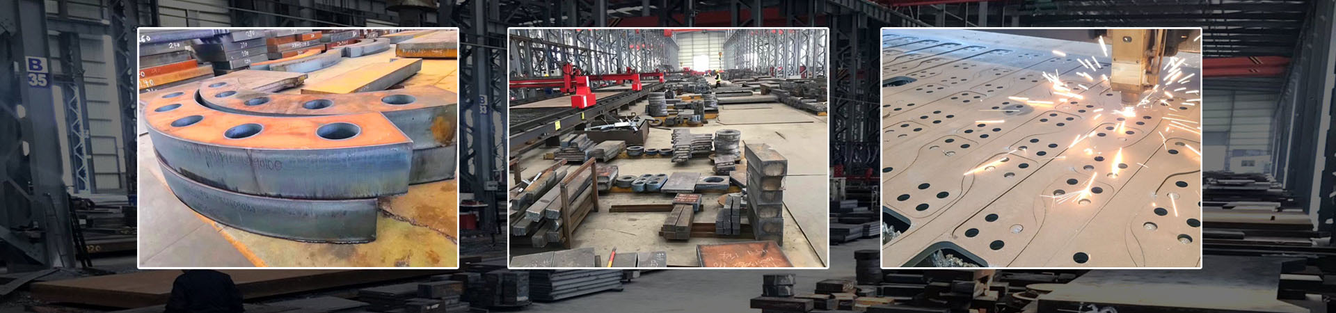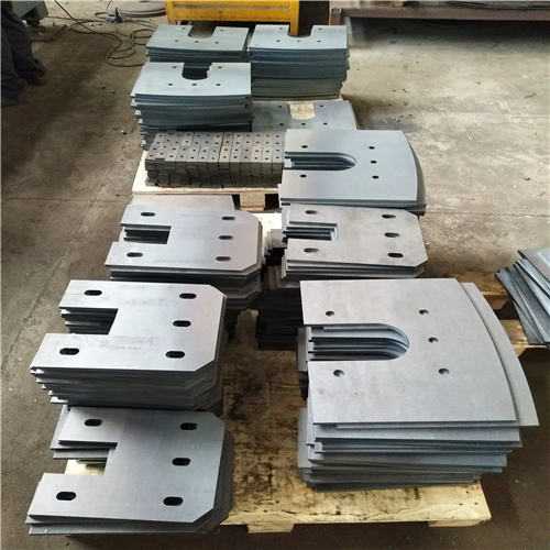
Precautions for Laser Cutting NM450 Wear-resistant Steel Plate

Packaging Details: Standard export seaworthy packing or as required.
Delivery Time:only one week for stock, customized products according to order negotiation.
Loading Port:Shanghai ,Qingdao,Tianjin .
payment terms:By T/T or L/C.
Supply capacity:1000MT/month.
MOQ: According to order negotiation.

Share

PRODUCT DESCRIPTION

NM450 is a quenched and tempered high-alloy wear plate with a hardness of 420–480HBW. It features high carbon equivalent, poor thermal conductivity and high thermal stress. Key risks during cutting include delayed cold cracks, hardened cutting edges, thermal deformation, bottom dross and incomplete cutting. Control measures are sorted into six sections as below.

1. Mandatory Requirements for Equipment and Auxiliary Gas

1.1 Laser Power (No Underpowered Configuration)

  • Thickness ≤12mm: Fiber laser with power ≥4000W
  • Thickness 12–20mm: 6000W or higher (6kW/8kW/12kW are mainstream models in the industry)
  • Thickness >20mm: Laser cutting has drastically reduced efficiency; plasma or flame cutting is preferred. If laser cutting is required, a 12kW+ high-power laser is necessary.

1.2 Selection of Auxiliary Gas by Application

  1. Oxygen Cutting (First choice for blanking, low cost) Oxygen purity ≥99.95%. Insufficient purity causes severe edge oxidation, thickened hardened heat-affected zones and high cracking tendency. Gas pressure shall be reduced by 10%–20% compared with carbon steel of the same thickness to lower heat input.
  2. High-purity Nitrogen (For finish parts free of oxidation) Nitrogen purity 99.999%. It delivers oxide-free cut edges and narrow heat-affected zones, yet supports thinner cutting thicknesses, slower cutting speed and higher cost. Suitable for workpieces requiring direct machining or welding after cutting.

1.3 Consumable Configuration

  • Adopt double-layer chromium-plated wear-resistant nozzles. Select one size larger bore than for Q235 carbon steel of equal thickness to reduce slag adhesion. High-temperature molten slag containing chromium and molybdenum causes nozzle wear 2–3 times faster than ordinary carbon steel cutting. Inspect and replace nozzles every shift.
  • Clean protective lenses regularly; high-hardness spatter easily burns lenses. Install high-capacity fume extraction equipment, as alloy fumes are irritant and toxic.

2. Pre-cut Plate Preparation (Core Measures to Prevent Cracks)

2.1 Plate Condition Inspection

  • Use flat raw plates. Stress-induced warped plates from rolling or storage shall be leveled first. Uneven suspension leads to local overheating, deformation and edge cracking.
  • Remove surface scale, rust and oil stains. Impurities cause uneven heat absorption, forming hard spots that act as crack initiation sources.

2.2 Preheating Process (Mandatory for Plates ≥10mm Thick)

Cracks generated on NM450 are delayed cold cracks, which may appear hours to 48 hours after cutting. Preheating is the most effective control method:

  1. Applicable scenarios: Plates ≥10mm thick, workshops with ambient temperature <10℃, mass production of thick plates
  2. Preheating temperature: 150–200℃ (measure backside temperature with a thermal gun; avoid local temperature exceeding 300℃ which reduces wear resistance via tempering)
  3. Heating method: Uniform sweeping with flame torches or electromagnetic heating mats; prohibit prolonged single-point heating
  4. Operation rule: Preheat the entire plate instead of only cutting lines; start cutting immediately after preheating—preheating loses effect once the plate cools down.

2.3 Nesting and Drawing Design Optimization

  1. Avoid sharp inner corners on contours; internal radii R ≥2mm. Sharp corners concentrate thermal stress and inevitably produce microcracks. If fillets are unavailable, add lead-out loops on outer contours and trim edges after separation.
  2. Apply micro-bridge connections (5–8mm tie points) for large and long workpieces to suppress overall thermal deformation. Separate parts only after full cooling post-cutting.
  3. Position piercing points away from finished edges and stressed workpiece borders. Use layered piercing for thick plates to mitigate instantaneous thermal shock.
  4. Cut large plates in segmented batches; reserve heat dissipation gaps between blocks to avoid accumulated heat.

3. In-process Parameter Control to Reduce Thermal Stress

3.1 Cutting Speed and Laser Power (Core Principle: Low Heat Input)

  • Reduce cutting speed by 20%–35% versus ordinary carbon steel of identical thickness, with slightly increased laser power. Excessively high speed leaves unremoved bottom dross; overly low speed widens the heat-affected zone and aggravates edge hardening.
  • Reduce speed and extend gas blow delay during piercing to prevent slag splashing and microcracks during thick plate piercing.
  • Avoid laser beam stagnation at any point. If cutting pauses or laser beam interrupts mid-process, reheat the local area before resuming cutting.

3. Focal Position and Cutting Height

Set negative focal point slightly below the plate bottom surface to ensure smooth slag removal from the underside. Adjust standoff height moderately with plate thickness to prevent nozzle collision with the plate.

3. Worktable Clamping

Fully attach the steel plate to support strips and secure with multi-point clamps. Suspension or vibration results in serrated cut edges and uneven stress cracking. Clear accumulated slag on support strips to eliminate local heat conduction obstruction.

4. Post-cut Cooling and Anti-crack Treatment (Critical Procedure)

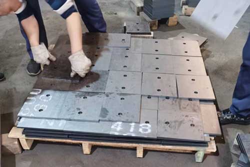
  1. Slow Cooling (Mandatory for Plates ≥10mm Thick) Do not expose freshly cut workpieces to open air cooling or spray water for rapid cooling. Immediately cover workpieces with thermal insulation cotton and cool slowly to room temperature for a minimum of 4 hours. Rapid cooling creates massive structural stress and penetrating delayed cracks.
  2. Post-heat Stress Relief (Required for Thick Plates & Welded Components) When workpieces cool down to approximately 100℃, uniformly heat cut edges with flame torches for 10–15 minutes at a controlled temperature of 180–220℃ to eliminate residual stress in the hardened edge layer. Allow natural slow cooling after post-heating.
  3. Static Aging Store high-risk thick plate parts for 24 hours before transferring, grinding or welding. This provides sufficient time for delayed cracks to emerge for early defective sorting.

5. Cut Edge Quality & Subsequent Machining Notes

  1. Removal of Edge Hardened Layer Laser cutting forms a 0.3–1mm high-hardness quenched heat-affected zone along cut edges. Direct welding or bending leads to cracking:
  • Welded parts: Grind cut edges completely to remove all oxidized hardened layers with a grinding depth ≥0.5mm.
  • Bent parts: Fully eliminate the hardened layer, enlarge bending radii and avoid cold bending of sharp corners.
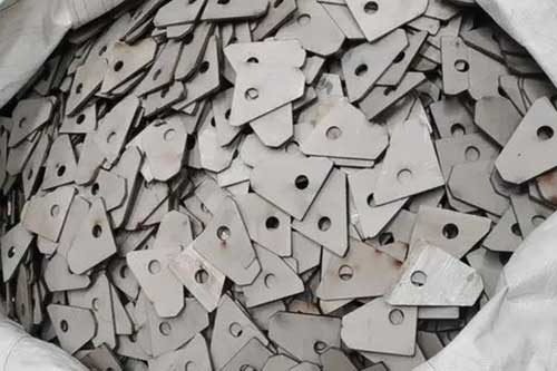
  1. Dross and Burr Cleaning Molten alloy slag on NM450 has strong adhesion; oxygen cutting commonly leaves heavy bottom dross. Clean thoroughly with wire wheels or grinders before assembly. Do not strike cut edges with hammers, as impact force triggers cracks.
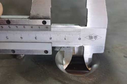
  2. Dimensional Compensation Thermal deformation is more severe than ordinary carbon steel. Reserve 0.05–0.1mm thermal shrinkage compensation for mass production. Measure dimensions only after full cooling of large plates.

6. Safety and Environmental Protection

  1. Personal protection: Wear laser safety goggles, flame-retardant workwear and high-temperature resistant gloves. High-temperature cutting spatter causes severe burns easily.
  2. Fume treatment: Activate high-power dust extraction systems. NM450 contains chromium and molybdenum; toxic alloy fumes generated at high temperatures must not be released without ventilation.
  3. Workpiece stacking: Isolate hot cut pieces before full cooling. Prevent hot edges from contacting water or damp ground. Increase preheating temperature by 20–30℃ for processing in low-temperature environments.

7. Common Defects and Countermeasures

  1. Microcracks / delayed cracking on cut edges: Increase preheating temperature, implement full post-cut slow cooling, eliminate sharp corners on drawings, lower cutting speed
  2. Severe bottom dross: Improve oxygen purity, optimize negative focal parameters, moderately raise gas pressure, reduce cutting travel speed
  3. Incomplete cutting & layered cross-sections: Insufficient laser power, clogged nozzles, low auxiliary gas pressure
  4. Workpiece warpage & deformation: Add micro-bridge connections, adopt segmented cutting, reduce total heat input, slow cool after cutting
  5. Excessively hardened cut surfaces: Switch to nitrogen cutting, grind off the hardened layer after cutting, narrow the heat-affected zone

Send a Message

If you are interested in our products and want to know more details,please leave a message here,we will reply you as soon as we can.

Whatsapp +8613526880645 Email hnsysteels@gmail.com Wechat