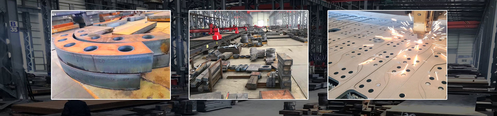
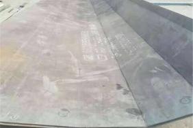
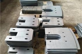
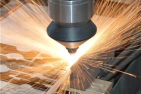
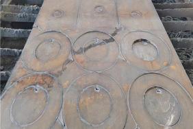
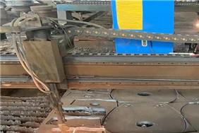
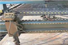
1. Core Difficulties in Cutting NM500 Material (Understand Material Before Process Control)
NM500 has a Brinell hardness of 470–540HBW with quenched martensitic structure. It features high hardness, brittleness, thermal sensitivity and high risk of microcracks after cutting:
- Secondary hardening occurs at cutting edges under high temperature, forming invisible cracks that easily cause edge chipping and fracture under impact service conditions.
- High thermal stress leads to warping and dimensional out-of-tolerance under unilateral continuous heating.
- High-hardness molten slag has poor fluidity, resulting in heavy dross on the bottom of thick plates and inclined cutting sections.
- Oxide scale on the plate surface reflects laser light, reducing laser absorption and causing piercing defects at starting points.
Applicable laser cutting thickness range: 6–25mm; plates thicker than 25mm are not recommended for laser cutting. Waterjet cutting or fine plasma cutting are preferred alternatives.
2. Full Set of Precautions for Laser Cutting NM500
2.1 Equipment & Consumable Selection Requirements
- Matching Laser Power
- 6–12mm: Fiber laser power ≥3000W
- 14–20mm: Fiber laser power ≥6000W
- 20–25mm: High-power laser of 12000W or above Forced cutting of thick plates with low power will produce rough sections, cracks and enlarged dimensional tolerances.
- Nozzles & Lenses
- Adopt thickened copper nozzles. The molten slag of wear-resistant steel is high-hardness, so nozzle wear rate is twice that of ordinary carbon steel. Inspect and replace nozzles every shift.
- Clean focusing lenses regularly. Smoke from wear plate processing easily coats lenses, causing energy attenuation and dimensional drift.
- Worktable Tooling Clamp the steel plate fully without overhang. Clear steel slag on the worktable to prevent inclined plates and inconsistent dimensional deviation between top and bottom surfaces.
2.2 Gas & Focal Position Process Control (Prevent Cracks & Control Roughness)
- Gas Selection (Core Parameter)
- High-precision cutting without hardened layer: High-pressure nitrogen (12–22bar). Inert gas cooling keeps heat-affected zone below 0.8mm, oxide-free cutting edges without secondary hardening, suitable for assembly and welding parts.
- Low-cost blanking: Oxygen. Exothermic reaction increases heat input and easily generates microcracks at cutting edges. Only applicable for rough blanking of non-stressed parts; post-grinding to remove hardened layer is mandatory. Nitrogen cutting is uniformly recommended for precision industrial workpieces.
- Focal Position
- Thin plate 6–10mm: Focus 0.5–1mm below the plate surface
- Medium plate 12–20mm: Focus at 1/2 of plate thickness
- Thick plate 20–25mm: Focus at 1/3 lower plate thickness to ensure uniform full penetration and reduce bevel angle.
2.3 Cutting Speed & Path Programming (Control Deformation & Cracks)
- Benchmark Cutting Speed Reduce speed by 20%–30% compared with carbon steel of identical thickness for stable cutting; avoid high-speed piercing and traversal.
- 6mm: 1.8–2.2m/min; 10mm: 1.0–1.4m/min; 16mm: 0.6–0.9m/min; 20mm: 0.3–0.5m/min
- Corner & Sharp Angle Treatment Activate 20% speed reduction at corners plus 0.5s cooling delay; enable cooling point function in software to blow cooling gas after laser shutdown, avoiding heat accumulation, edge spalling and microcracks at corners.
- Nesting & Micro-joint Design (Control Thermal Deformation)
- Add 0.8–1.2mm micro-joints for long strip or large-size workpieces instead of full cutting at once, to avoid twisting from instantaneous stress release.
- Adopt symmetrical staggered cutting paths to prevent long-term unilateral heating.
- Segment cutting for large plates with 5–10mm reserved connecting strips; separate all workpieces uniformly after full cutting.
- Piercing & Termination Parameters 0.05–0.1s laser delay at piercing to guarantee full penetration of starting points; 0.1–0.15s gas delay after laser shutdown to eliminate bottom dross and missing corners at termination.
2.4 Temperature Control & Cooling (Primary Measure to Eliminate Cracks)
- Forced air cooling or water quenching is prohibited. Excessive temperature difference directly induces quenching cracks.
- Cool workpieces naturally to room temperature (minimum 30min) before unloading; hoisting immediately after cutting is forbidden.
- Intermittently stop production to cool the worktable during mass processing of plates ≥20mm to avoid continuous heat accumulation.
2.5 Pre-processing & Post-processing of Steel Plates
- Pre-cutting treatment: Grind off heavy oxide scale and anti-rust paint on plate surfaces to reduce light reflection and eliminate burn marks at piercing points.
- Mandatory post-cutting procedures:
- Nitrogen cutting: Light grinding to remove bottom dross only.
- Oxygen cutting: Grind 1–2mm hardened layer on cutting edges, otherwise cracking will occur during service.
- Workpieces requiring flaw detection: Conduct magnetic particle inspection for edge microcracks after grinding.
2.6 Avoidance of Common Defects
- Edge microcracks: Excessive heat input, oxygen cutting or rapid cooling → Switch to nitrogen cutting, reduce cutting speed and apply natural slow cooling.
- Heavy bottom dross: Insufficient gas pressure, offset focal position or excessive cutting speed → Increase nitrogen pressure and readjust focal position.
- Unstable dimensional fluctuation: Unclamped plates, contaminated lenses or worn nozzles → Fasten tooling, clean optical path and replace worn nozzles.
- Workpiece warping: Continuous unilateral cutting, missing micro-joints or rapid cooling → Adopt symmetrical cutting paths, add micro-joints and natural slow cooling.
3. Cutting Accuracy Comparison Table for NM500 of Different Thicknesses (Industrial Measured Standards)
Prerequisites: Fiber laser ≥6000W, nitrogen cutting, machine repeat positioning accuracy ±0.03mm, flat clamped plates and natural slow cooling
表格
| Plate Thickness |
Overall Dimension Tolerance |
Inner Hole/Small Hole Tolerance |
Cutting Edge Perpendicularity (Bevel Angle) |
Width of Heat-Affected Zone |
Section Roughness Ra |
Kerf Width |
| 6–10mm Thin Plate |
±0.05~±0.08mm |
±0.08~±0.10mm |
≤0.5° |
0.3–0.6mm |
1.6–3.2μm |
0.15–0.25mm |
| 12–16mm Medium Plate |
±0.08~±0.10mm |
±0.10~±0.12mm |
≤0.8° |
0.5–0.8mm |
3.2–6.3μm |
0.25–0.35mm |
| 18–20mm Thick Plate |
±0.10~±0.15mm |
±0.12~±0.18mm |
≤1.2° |
0.7–1.0mm |
6.3μm |
0.35–0.45mm |
| 22–25mm Laser Limit Thickness |
±0.15~±0.20mm |
±0.18~±0.25mm |
≤1.8° |
0.9–1.2mm |
6.3–12.5μm |
0.45–0.55mm |
Supplementary Accuracy Explanation
- Mechanical positioning accuracy of machine tools: Theoretical upper limit is ±0.02–0.03mm repeat positioning. Actual tolerance is determined by plate thermal deformation and process parameters; tolerance expands with increasing plate thickness.
- Accuracy attenuation of oxygen cutting: Tolerance is 0.05–0.1mm larger than nitrogen cutting for identical thickness, with larger bevel angle and doubled heat-affected zone width.
- Minimum small hole limit: Holes ≥φ3 are feasible for plates ≤12mm; minimum hole diameter for 16–25mm plates shall be at least 1.2 times plate thickness. Undersized holes will form ellipses and exceed dimensional tolerance.
- Reference Comparison with Other Cutting Processes
- Fine plasma cutting: Tolerance ±0.3–0.5mm, bevel angle 2–4°
- Waterjet cold cutting: Tolerance ±0.10–0.15mm, zero heat-affected zone, ideal for high-precision wear-resistant plates thicker than 25mm
4. Machining Selection Recommendations
- 6–20mm plates for precision flanges, bearing housings, excavator wear liners and bolt hole parts: Nitrogen fiber laser cutting, high precision, crack-free and one-step forming.
- 20–25mm plates for low-precision blanking: 12000W+ laser with strictly controlled cutting speed and cooling process.
- Plates thicker than 25mm, impact-resistant wear parts with zero tolerance for thermal quenching cracks: Directly select waterjet cutting to eliminate heat-affected zones and crack risks.